

Standard Penetration Testing remains one of the most widely used in-situ soil testing methods in geotechnical engineering. Since its development in the early 1900s, spt testing has become a cornerstone of site characterization, providing essential data for foundation design, liquefaction assessment, and soil classification. The test's simplicity, relatively low cost, and extensive historical database make it an attractive option for projects ranging from residential developments to major infrastructure works. However, the reliability of spt testing depends heavily on proper execution, equipment calibration, and thoughtful interpretation of results. Understanding both the capabilities and limitations of this method is essential for engineers, contractors, and project owners seeking defensible geotechnical data.
Understanding the SPT Testing Process
The standard penetration test involves driving a split-spoon sampler into soil using a standardized hammer and measuring the resistance to penetration. The test procedure follows ASTM D1586 or equivalent national standards, which specify equipment dimensions, drop height, and operational requirements.
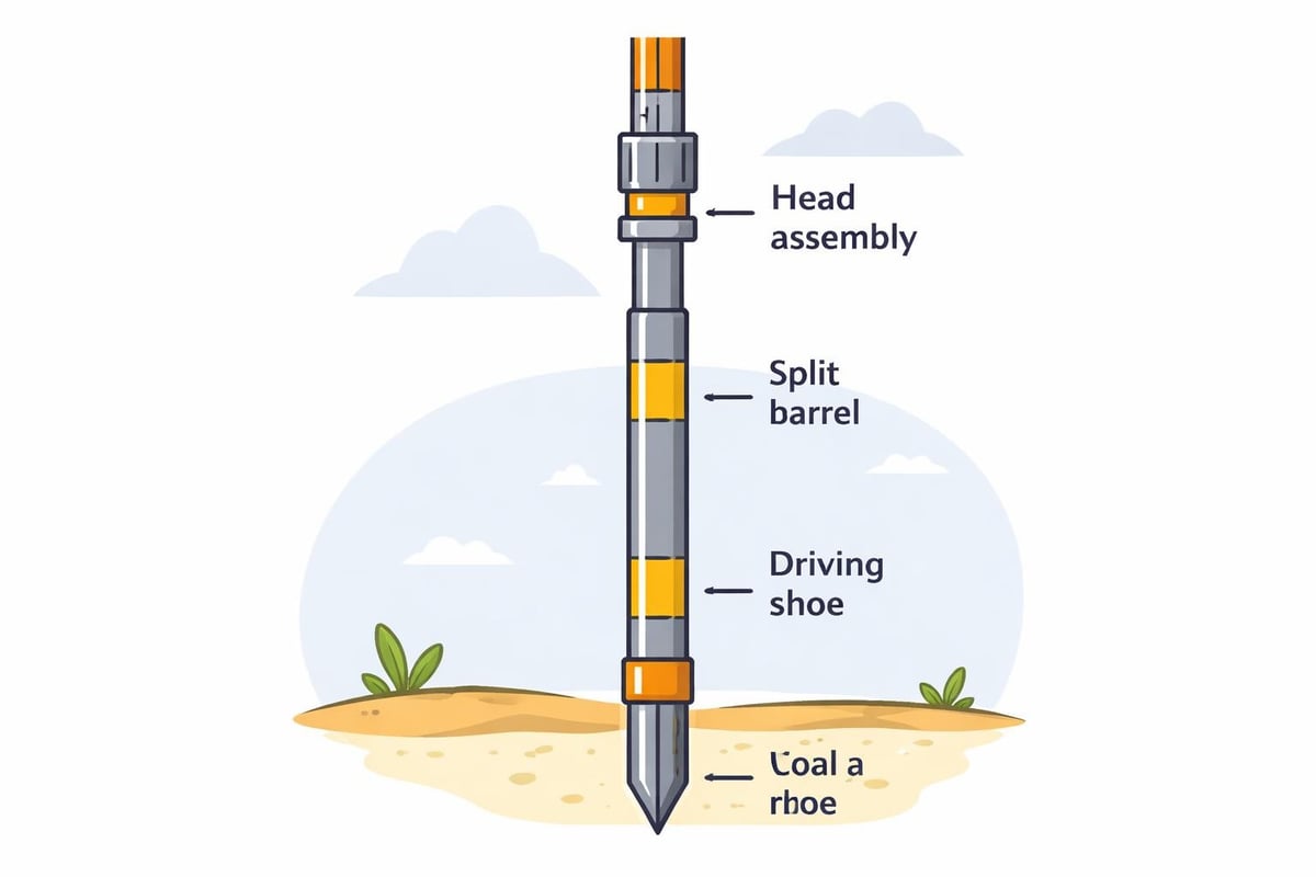
During testing, a drill rig advances a borehole to the desired depth using appropriate drilling methods. Once the borehole reaches the test elevation, crews remove the drill bit and lower a split-spoon sampler attached to drill rods. The sampler consists of a driving shoe, a split barrel for soil recovery, and a head assembly that connects to the rods.
Equipment Components and Specifications
The standardized equipment ensures consistency across different testing operations:
- Hammer assembly: 140-pound (63.5 kg) weight with automatic or manual release mechanism
- Drop height: 30 inches (762 mm) measured from hammer to anvil
- Split-spoon sampler: 2-inch outer diameter, 1.375-inch inner diameter, 18-24 inch length
- Drill rods: Standard weight with proper threading and minimal wear
The test procedure requires driving the sampler in three 6-inch (152 mm) increments. Operators record the number of blows required for each increment separately. The N-value, or blow count, represents the number of blows needed to drive the sampler the final 12 inches (305 mm). This N-value becomes the primary index for soil strength and density characterization.
Field Procedures and Quality Control
Proper field execution significantly impacts data reliability. Drill crews must maintain vertical alignment of the drill string, ensure the sampler seats properly at the bottom of the borehole, and apply consistent hammer drops. The drilling method used to advance the borehole also affects results, as excessive disturbance can alter in-situ soil conditions.
Common drilling methods include hollow-stem augers, mud rotary, and air rotary. Each method has advantages depending on soil conditions, groundwater levels, and project requirements. Hollow-stem augers minimize disturbance in cohesive soils and maintain borehole stability without drilling fluid. Mud rotary provides excellent cutting action in harder formations but requires careful mud management to prevent sample contamination.
Applications in Geotechnical Engineering
SPT testing serves multiple purposes in geotechnical investigations, providing data that influences design decisions across various project types. The blow count correlates with soil properties including relative density, undrained shear strength, and bearing capacity.
Foundation Design and Analysis
Foundation engineers rely on spt testing data to estimate allowable bearing pressures, settlement characteristics, and foundation depth requirements. Empirical correlations convert N-values to engineering parameters used in bearing capacity calculations and settlement predictions.
For cohesionless soils, the corrected N-value helps determine relative density, which influences friction angle selection. In cohesive soils, correlations exist between N-values and undrained shear strength, though direct shear testing provides more reliable strength parameters for critical projects.
The soil samples recovered during testing allow visual classification, moisture content determination, and selection of specimens for laboratory testing. This combination of field resistance data and recovered samples provides a comprehensive picture of subsurface conditions. When integrated with comprehensive geotechnical engineering services, spt testing forms the foundation for safe, economical structure designs.
| Soil Type | N-value Range | Relative Density/Consistency | Typical Bearing Capacity (kPa) |
|---|---|---|---|
| Sand | 0-4 | Very loose | 50-100 |
| Sand | 4-10 | Loose | 100-200 |
| Sand | 10-30 | Medium dense | 200-400 |
| Sand | 30-50 | Dense | 400-600 |
| Clay | 0-2 | Very soft | 25-50 |
| Clay | 2-4 | Soft | 50-100 |
| Clay | 4-8 | Medium stiff | 100-200 |
| Clay | 8-15 | Stiff | 200-400 |
Liquefaction Potential Assessment
Seismic design requires evaluation of liquefaction susceptibility in saturated cohesionless soils. The corrected SPT blow count, designated as (N1)60, serves as the primary parameter in simplified liquefaction triggering analyses. This correction adjusts the field N-value for overburden pressure, hammer energy, borehole diameter, rod length, and sampler type.
The liquefaction assessment process compares the cyclic resistance ratio (CRR), estimated from corrected N-values, with the cyclic stress ratio (CSR) imposed by the design earthquake. Projects in seismically active regions routinely specify spt testing at close vertical intervals in liquefiable zones to accurately characterize resistance profiles.
Factors Affecting Test Reliability
Despite its widespread use, spt testing exhibits significant variability due to equipment differences, procedural variations, and operator technique. Recognizing these factors helps engineers interpret results appropriately and specify testing requirements that maximize data quality.
Hammer Energy Transfer
One of the most critical variables in spt testing is the actual energy delivered to the drill rods. The theoretical maximum energy equals the hammer weight multiplied by drop height, but actual energy transfer typically ranges from 30% to 90% of theoretical. This variation stems from hammer type, release mechanism, anvil condition, and rod system characteristics.
Energy calibration procedures have become standard practice for quality-conscious projects. Calibration involves measuring actual energy delivery using accelerometers and force transducers mounted on the drill rods. The measured energy ratio allows correction of field N-values to a standard 60% energy level, designated as N60.

Different hammer systems produce characteristic energy ratios:
- Safety hammers with rope and cathead: 45-80%
- Donut hammers: 30-60%
- Automatic trip hammers: 70-90%
- Free-fall hammers: 80-100%
The importance of energy standardization cannot be overstated when comparing results from different drilling contractors or correlating with published data. Without energy correction, a blow count of 15 could represent significantly different soil resistance depending on the hammer system used.
Correction Factors and Normalized Values
Engineers apply multiple correction factors to convert field N-values into standardized parameters suitable for analysis. The most comprehensive correction produces (N1)60, which accounts for:
- Overburden pressure: CN factor normalizes N-values to a reference effective stress of 1 atmosphere
- Hammer energy: CE factor adjusts for actual energy delivery
- Borehole diameter: CB factor accounts for hole diameter effects
- Rod length: CR factor compensates for energy loss in short rod strings
- Sampler type: CS factor adjusts for liner use or non-standard samplers
The equation for corrected blow count is: (N1)60 = N × CN × CE × CB × CR × CS
These corrections significantly impact interpretation, particularly in loose sands at shallow depth or dense sands at significant depth. Failure to apply appropriate corrections can lead to unconservative foundation designs or inaccurate liquefaction assessments.
Limitations and Alternative Testing Methods
While spt testing provides valuable information economically, engineers must recognize its limitations. The test provides limited data points compared to continuous profiling methods, disturbs the soil during driving, and shows high variability even in uniform deposits.
When SPT Testing Falls Short
Certain soil conditions and project requirements exceed the capabilities of standard penetration testing:
- Very soft clays: Blow counts below 2 provide minimal discrimination
- Dense gravels: Refusal or erratic blow counts offer limited quantitative data
- Detailed stratigraphy: 5-foot test intervals miss thin layers and gradational contacts
- Precise strength parameters: Empirical correlations lack the accuracy of laboratory testing
- Stiffness characterization: SPT provides no direct measurement of soil modulus
The critical assessment of SPT practices highlights concerns about over-reliance on a test with inherent limitations. Projects requiring high-quality geotechnical parameters often supplement or replace spt testing with cone penetration testing (CPT), dilatometer testing (DMT), or direct laboratory testing on high-quality samples.
Complementary Investigation Methods
A comprehensive geotechnical investigation typically combines multiple testing approaches. CPT provides continuous profiling with better repeatability and theoretical basis for interpretation. Vane shear testing directly measures undrained strength in soft clays. Pressuremeter testing determines in-situ stress-strain behavior.
The selection of testing methods depends on soil conditions, project requirements, budget constraints, and regulatory expectations. Transportation projects may emphasize construction material testing alongside subsurface investigation. Environmental projects combine borings with groundwater monitoring and contaminant assessment.
| Testing Method | Advantages | Limitations | Typical Applications |
|---|---|---|---|
| SPT | Economical, provides samples, extensive database | High variability, disturbs soil, limited in extreme conditions | General site characterization, foundation design |
| CPT | Continuous data, repeatable, rapid | No soil samples, requires special equipment, limited in dense gravel | Detailed profiling, liquefaction assessment |
| Vane Shear | Direct strength measurement | Limited to soft clays, small strain range | Undrained strength in cohesive soils |
| Pressuremeter | Measures modulus directly | Expensive, requires skilled operators | Stiffness characterization for settlement analysis |
Best Practices for Specification and Interpretation
Maximizing the value of spt testing requires careful specification, quality control during execution, and thoughtful interpretation of results. Project specifications should address equipment requirements, procedural standards, correction factors, and reporting expectations.
Specification Guidelines
Clear specifications reduce variability and ensure data quality. Essential elements include:
- Reference to applicable standards (ASTM D1586, ISO 22476-3, or equivalent)
- Requirements for automatic trip hammers or energy measurement
- Minimum test frequency (typically every 5 feet or at soil type changes)
- Drilling method restrictions in sensitive soils
- Sample recovery and classification requirements
- Correction factors to be applied in reporting
Projects with critical foundations or seismic concerns should mandate energy calibration. The specification should require hammer energy verification at project start and periodic recalibration throughout the investigation program.

Interpretation Strategies
Converting blow counts to design parameters requires judgment informed by local experience, published correlations, and understanding of soil behavior. Engineers should:
- Consider multiple correlations and compare results
- Calibrate correlations using laboratory test data when available
- Account for soil plasticity, mineralogy, and stress history
- Recognize outliers and investigate causes (gravel lenses, drilling disturbance, equipment malfunction)
- Compare results with regional databases and similar projects
The reliability of SPT data varies with soil type and application. Conservative approaches apply safety factors appropriate to data uncertainty. Critical projects justify supplemental investigation or load testing to reduce uncertainty.
Integration with Construction and Monitoring
SPT testing serves not only design but also construction verification and quality assurance. Understanding how subsurface conditions vary across a site helps contractors plan excavations, predict groundwater inflows, and select appropriate equipment.
Construction Planning Support
Blow count profiles inform contractors about anticipated drilling rates, excavation difficulty, and dewatering requirements. Dense sands with N-values exceeding 50 may require pre-drilling for piles or sheet piles. Very loose sands with low N-values signal potential excavation instability requiring shoring.
The soil samples recovered during testing support construction material evaluation when borrowed earth materials or on-site soils are considered for controlled fill. Classification and compaction testing on SPT samples help assess material suitability early in project development.
Foundation contractors use spt testing data to verify that bearing strata match design assumptions. If excavations reveal conditions different from predicted, additional testing confirms bearing capacity and allows foundation redesign if necessary.
Quality Assurance During Projects
Some projects specify additional spt testing during construction to verify soil improvement, confirm foundation bearing depths, or investigate anomalous conditions. Post-grouting verification, stone column installation control, and deep soil mixing quality checks may incorporate penetration testing alongside other methods.
The combination of pre-construction investigation and construction-phase testing builds confidence in ground conditions and supports risk management. Unexpected conditions discovered during construction receive prompt evaluation through additional testing, avoiding costly delays and design modifications.
Regional Considerations and Standards
While spt testing follows broadly similar procedures worldwide, regional standards, correlations, and practices reflect local geology, experience, and regulatory frameworks. Familiarity with regional approaches ensures appropriate test execution and interpretation.
North American Practice
In the United States and Canada, ASTM D1586 provides the standard test method reference. Canadian practice often specifies energy measurement given the significant impact on data reliability. Regional geological conditions influence correlation selection-glacial tills behave differently than alluvial deposits, requiring locally developed relationships.
Transportation agencies maintain specifications addressing testing frequency, sampling intervals, and reporting requirements. State departments of transportation publish standard specifications incorporating lessons learned from decades of highway construction across varied geological settings.
International Standards and Variations
European practice follows ISO 22476-3, which specifies similar basic procedures but includes different equipment tolerances and reporting conventions. The practical aspects outlined by UK practitioners demonstrate how regional experience shapes testing approaches.
Asian practice varies by country, with some regions favoring alternative methods like CPT while others rely heavily on SPT. Japanese practice developed extensive correlations for seismic design given the country's earthquake exposure and saturated alluvial deposits.
Engineers working across borders must recognize these variations and select correlations appropriate to the regional context. The general overview provided by technical references offers starting points for understanding global practices.
Advancing Technology and Future Directions
While the fundamental spt testing procedure has remained largely unchanged for decades, equipment improvements and data processing advances continue to enhance reliability and value. Modern drilling rigs, instrumented hammers, and digital data acquisition systems reduce variability and improve documentation.
Instrumented SPT Systems
Advanced systems incorporate load cells and accelerometers that measure energy delivery in real time. These systems eliminate the need for separate energy calibration mobilizations and provide continuous quality control throughout drilling programs. Automated blow count recording reduces transcription errors and improves data traceability.
Some systems integrate GPS positioning, electronic field logs, and cloud-based data management, allowing engineers to review results daily and adjust investigation programs responsively. This real-time feedback accelerates project schedules and optimizes boring locations based on emerging subsurface understanding.
Enhanced Correlations and Machine Learning
The accumulation of large SPT databases enables statistical analysis and development of refined correlations. Machine learning approaches identify patterns in complex datasets, potentially improving parameter predictions from blow count data. Regional databases comparing SPT results with laboratory tests and field performance strengthen correlation reliability.
However, fundamental limitations remain-spt testing will never match the accuracy of direct laboratory measurement or the continuity of electronic profiling methods. The test's value lies in its economic provision of useful information across the widest possible range of projects and soil conditions.
Standard penetration testing continues to provide essential subsurface data for foundation design, liquefaction assessment, and site characterization despite inherent limitations. Success requires proper equipment, standardized procedures, appropriate corrections, and thoughtful interpretation informed by project requirements and local geology. ZALIG Consulting Ltd integrates spt testing with comprehensive geotechnical investigation services, laboratory analysis, and engineering design to deliver defensible solutions for civil infrastructure, commercial development, and industrial projects. Our experienced field crews and engineers ensure quality data collection and interpretation that supports safe, economical designs and regulatory approvals.