

Pile Foundations: Design, Types & Engineering Essentials
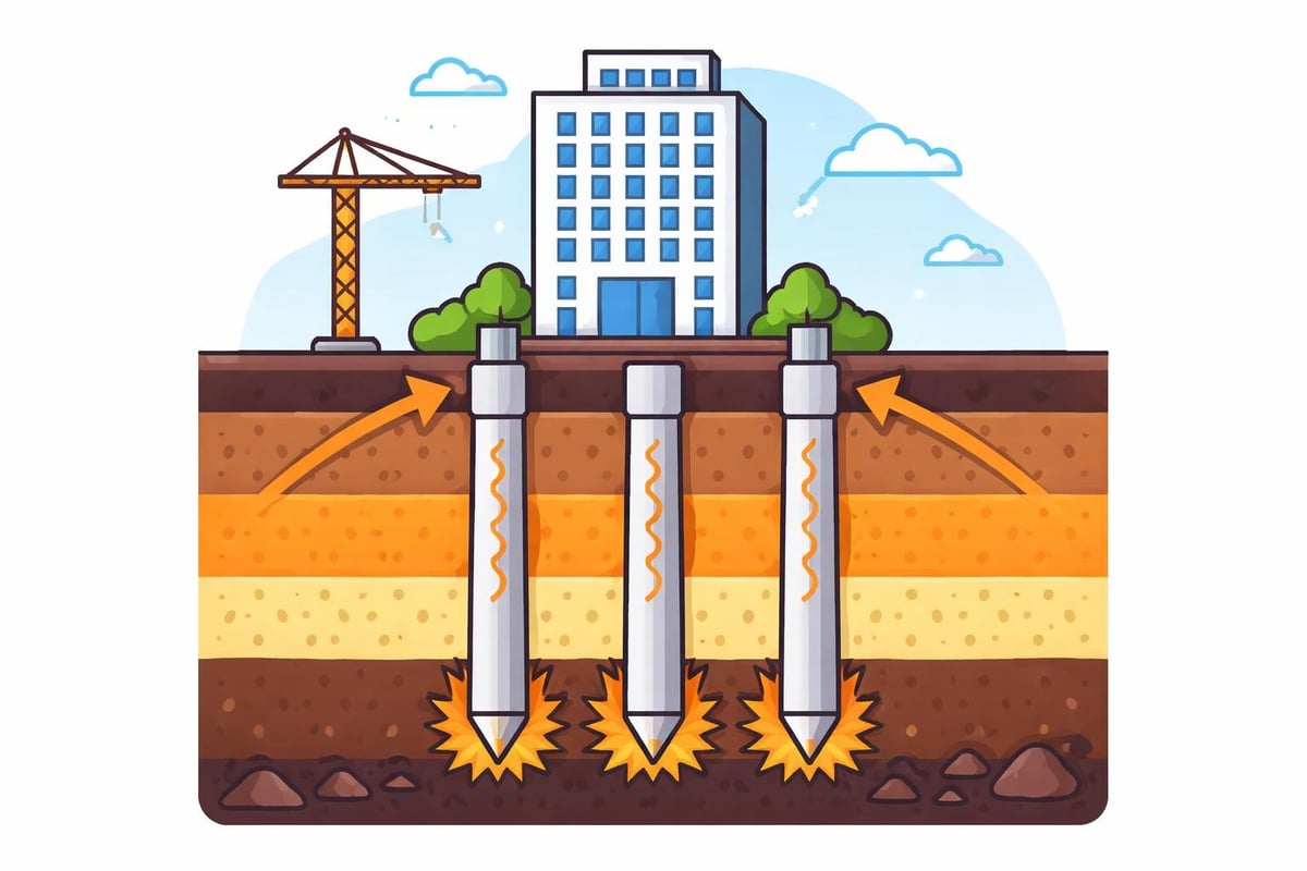
Pile foundations represent one of the most critical deep foundation systems in modern civil engineering, transferring structural loads through weak or compressible soil layers to competent bearing strata at depth. These vertical or inclined structural members are essential when shallow foundation systems cannot provide adequate bearing capacity or when settlement control is paramount. From high-rise buildings and bridges to industrial facilities and marine structures, pile foundations enable safe, economical construction across diverse ground conditions. Understanding the design principles, installation methods, and performance characteristics of these systems is fundamental for engineers, owners, and contractors engaged in infrastructure development.
Understanding Pile Foundation Mechanics
Pile foundations derive their load-carrying capacity through two primary mechanisms: end bearing and skin friction. End bearing piles transmit loads directly to a strong stratum through the pile tip, functioning similarly to a column that extends through weak soil to reach competent bedrock or dense granular material. Skin friction piles, conversely, develop capacity through adhesion and friction along the embedded pile shaft, mobilizing resistance throughout the soil profile.
Most pile installations exhibit combined behavior, drawing capacity from both mechanisms simultaneously. The relative contribution of each component depends on soil stratification, pile geometry, and installation method. Soil mechanics principles govern this load transfer, with effective stress, soil stiffness, and lateral earth pressure coefficients determining the ultimate pile capacity.
Geotechnical Site Investigation Requirements
Comprehensive subsurface investigation forms the foundation of rational pile design. Boring programs must extend below the anticipated pile tip elevation to characterize bearing strata and identify potential weak zones that could compromise performance. Standard Penetration Test (SPT) values, cone penetration testing (CPT) data, and undrained shear strength measurements provide the empirical and analytical parameters required for capacity calculations.
Laboratory testing programs should address soil classification, consolidation characteristics, and strength parameters. For projects involving driven piles, soil density and gradation analyses help predict drivability and estimate driving resistance. Groundwater levels significantly influence both installation feasibility and long-term performance, particularly regarding negative skin friction in consolidating clay deposits.
Engineers must evaluate potential construction impacts including ground vibration, lateral displacement, and pore pressure generation during pile installation. These factors affect adjacent structures and inform the selection of appropriate pile types and installation methods. Advanced geotechnical laboratory testing provides the detailed soil characterization necessary for optimizing pile foundation design.
Pile Foundation Types and Selection Criteria
The construction industry employs numerous pile types, each suited to specific ground conditions, structural requirements, and project constraints. Selection criteria encompass bearing capacity requirements, installation constraints, environmental considerations, and economic factors.
Driven Pile Systems
Driven piles remain among the most widely used deep foundation elements. Steel H-piles offer high structural capacity, excellent penetration through dense or obstructed soils, and minimal material displacement. Their open section allows for splicing and enables end bearing in rock when properly seated.
Precast concrete piles provide high compressive strength, durability, and quality control through factory production. These elements suit projects requiring substantial capacity and where driving vibration is acceptable. Prestressed concrete piles incorporate high-strength steel strands that resist handling stresses and increase flexural capacity.
Timber piles represent the traditional foundation solution, offering cost-effectiveness for moderate load applications in areas with accessible timber resources. Their use has declined with concrete and steel alternatives, though they remain viable for certain marine and temporary works applications.
Cast-in-Place Pile Solutions
Drilled shaft foundations, also termed bored piles or caissons, involve excavating a cylindrical hole and filling it with reinforced concrete. These systems minimize vibration and noise, making them suitable for urban environments and sites adjacent to sensitive structures. Large-diameter shafts can develop enormous capacity, supporting the heaviest structural loads.
Auger-cast piles (continuous flight auger piles) combine drilling and concreting in a single continuous operation. The hollow-stem auger penetrates to design depth while displaced soil travels up the auger flights. Concrete pumps through the hollow stem as the auger withdraws, creating a continuous concrete column. This method produces minimal spoil and reduces environmental impact.
Micropiles represent a specialized category featuring high-capacity, small-diameter drilled and grouted piles. These elements excel in restricted access conditions, underpinning applications, and ground improvement projects. Their installation produces minimal disturbance and enables work within existing structures.
| Pile Type | Primary Advantage | Typical Capacity Range | Installation Consideration |
|---|---|---|---|
| Steel H-Pile | Penetration through obstructions | 500-2000 kN | High vibration and noise |
| Precast Concrete | Quality control, durability | 800-3500 kN | Requires heavy equipment |
| Drilled Shaft | Minimal vibration, high capacity | 2000-20000+ kN | Groundwater management critical |
| Auger-Cast | Low spoil, moderate noise | 600-2000 kN | Concrete quality verification needed |
| Micropile | Access constraints, underpinning | 300-1000 kN | High cost per unit capacity |
Design Methodologies and Capacity Determination
Pile capacity analysis employs static analysis methods, dynamic analysis during installation, and load testing protocols. Each approach provides distinct insights into foundation performance and contributes to comprehensive design verification.
Static Analysis Approaches
Static capacity calculations rely on empirical correlations, analytical methods, and finite element analysis. The design principles and construction challenges documented by the International Society for Soil Mechanics and Geotechnical Engineering establish the theoretical framework for these calculations.
Ultimate capacity represents the maximum load a pile can sustain before failure. Engineers apply appropriate factors of safety to determine allowable design loads. For end bearing piles in cohesionless soils, bearing capacity factors derived from SPT N-values or CPT cone resistance provide capacity estimates. In cohesive soils, undrained shear strength governs end bearing capacity through bearing capacity theory.
Shaft friction calculations depend on soil type and installation method. Driven piles in sand develop shaft resistance proportional to vertical effective stress and a lateral earth pressure coefficient influenced by installation effects. In clay, adhesion factors relate shaft resistance to undrained shear strength, with values adjusted for pile type and installation method.
Negative skin friction presents a critical consideration in consolidating soil deposits. Settlement of compressible layers relative to the pile applies downward drag loads that must be considered in design. This phenomenon commonly occurs in reclaimed land, areas with high groundwater table drawdown, or locations with recent fill placement.
Dynamic Analysis and Pile Driving
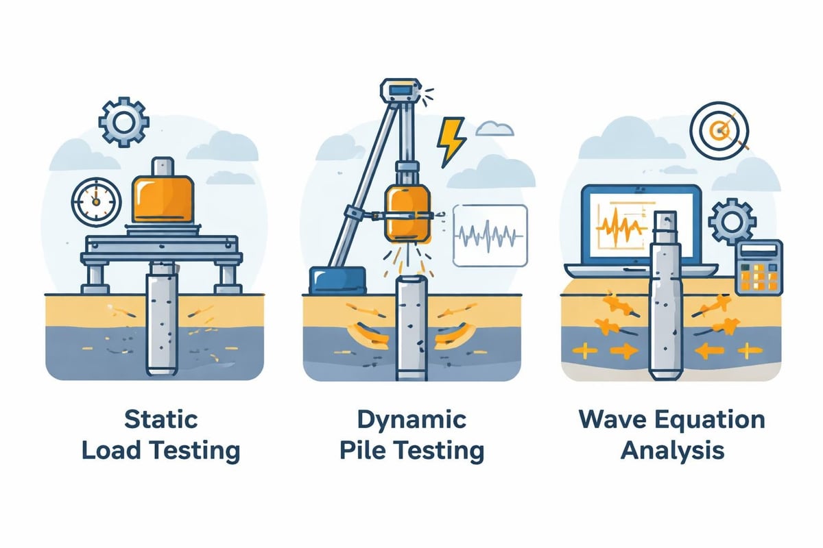
Wave equation analysis predicts pile drivability and estimates capacity from driving resistance. This forward analysis models the pile-hammer-soil system to evaluate stresses developed during driving and optimize hammer selection. The analysis prevents pile damage from overstressing and ensures adequate hammer energy for installation to required depths.
Dynamic load testing during installation provides real-time capacity evaluation. High strain dynamic testing employs accelerometers and strain transducers attached to the pile head, recording stress waves during impact. Signal matching analysis determines capacity, assesses pile integrity, and evaluates hammer performance.
Case Pile Wave Analysis Program (CAPWAP) represents the industry-standard signal matching technique, iteratively adjusting soil resistance distribution until calculated force and velocity records match measured values. This analysis provides detailed capacity distribution along the pile shaft and at the tip.
Installation Considerations and Quality Assurance
Successful pile installation requires careful planning, appropriate equipment selection, and comprehensive quality control protocols. Installation challenges vary significantly with pile type, ground conditions, and project-specific constraints.
Driven Pile Installation Control
Driving criteria typically specify a target blow count over a defined penetration distance. Engineers establish these criteria through wave equation analysis and correlate them to design capacity. Driving logs document hammer type, cushion condition, blow counts, pile penetration, and set values throughout installation.
Installation monitoring identifies anomalies including hard driving indicating obstructions or dense layers, soft driving suggesting inadequate bearing, and driving refusal preventing achievement of design depth. These conditions require engineering evaluation and potential design modifications.
Pile damage during driving represents a persistent concern. Buckling can occur in slender piles subjected to eccentric loading or lateral deflection. Tension stresses from reflected stress waves may crack concrete piles. Head damage results from improper cushioning or misalignment. Pre-drilling, pile driving analyzer monitoring, and appropriate hammer selection mitigate these risks.
Cast-in-Place Quality Verification
Drilled shaft construction demands rigorous inspection protocols. Borehole stability, base cleanliness, reinforcing cage placement, and concrete quality critically affect performance. Temporary casing or drilling fluids maintain borehole stability in unstable or saturated soils.
Bottom cleanout immediately before concreting removes loose material and ensures proper end bearing. Inadequate cleanout creates a soft zone that reduces capacity and increases settlement. Inspection methods include weighted tape soundings, camera surveys, and geophysical techniques.
Concrete placement typically employs tremie methods to prevent segregation and soil contamination. Continuous placement prevents cold joints, and slump must balance workability with strength requirements. Thermal of Hydration monitoring in large diameter shafts prevents cracking from temperature differentials.
For projects requiring pile foundation inspection and verification, specialized deep foundation services provide the expertise needed to ensure installation quality and capacity achievement across diverse pile types and ground conditions.
Load Testing Programs and Performance Verification
Static load testing provides the most direct measurement of pile capacity and load-settlement behavior. Test programs typically include proof tests verifying production pile capacity and prototype tests validating design assumptions on larger projects.
Static Load Test Methods
Maintained load tests apply incremental loads with settlement monitored until stabilization occurs at each increment. The procedure continues to failure or a predetermined maximum load. This method provides comprehensive load-settlement data suitable for settlement-sensitive structures.
Quick load tests apply incremental loads at fixed time intervals regardless of settlement stabilization. This approach reduces testing duration while providing capacity estimates suitable for many applications. However, the method may not fully capture time-dependent behavior in clay soils.
Osterberg cell tests (O-cell tests) offer an economical alternative to traditional top-down loading. A hydraulic jack installed near the pile base applies bidirectional load, mobilizing shaft resistance upward and end bearing downward. This self-reacting system eliminates reaction frame costs and enables testing of high-capacity piles.
- Maintained load tests provide comprehensive settlement data
- Quick tests reduce time and cost for capacity verification
- Bidirectional tests eliminate expensive reaction systems
- Instrumented test piles measure load transfer distribution
- Multiple test methods optimize verification for project requirements
Interpretation of Load Test Results
Load-settlement curve analysis determines ultimate capacity using various failure criteria. The Davisson offset limit defines failure as the settlement corresponding to elastic compression plus a specified offset. Alternative criteria including Chin’s method and DeBeer’s method provide additional interpretation approaches.
Pile group effects modify individual pile capacity and settlement behavior. Spacing, configuration, and load distribution influence group efficiency. Closely spaced piles in clay may exhibit reduced capacity due to overlapping stress zones. Block failure mechanisms require evaluation when spacing falls below threshold values.
| Test Method | Duration | Cost Relative | Primary Data | Best Application |
|---|---|---|---|---|
| Maintained Load | 2-5 days | Highest | Full load-settlement curve | Settlement-sensitive projects |
| Quick Load | 4-8 hours | Moderate | Capacity estimate | Routine capacity verification |
| Osterberg Cell | 1-2 days | High | Bidirectional response | High capacity, cost savings on reaction |
| Dynamic Testing | Minutes per pile | Lowest | Capacity estimate, integrity | Production pile verification |
Special Considerations in Pile Foundation Engineering
Certain conditions and applications demand specialized analysis and construction techniques beyond conventional pile foundation practice. These scenarios require enhanced engineering scrutiny and adapted methodologies.
Seismic Design Requirements
Earthquake loading subjects pile foundations to complex lateral and axial loading combinations. Liquefaction of saturated granular soils dramatically reduces lateral support and can induce excessive bending moments. Kinematic interaction from ground displacement applies loads independent of superstructure response.
Seismic design requires evaluation of lateral pile capacity, structural detailing for ductility, and consideration of soil-pile interaction effects. Moment connections between piles and pile caps must develop plastic hinges while maintaining vertical load capacity. Analysis methods range from simplified pseudo-static approaches to sophisticated nonlinear dynamic analysis.
Pile spacing and group configuration influence seismic performance. Increased spacing reduces group interaction effects and improves lateral resistance. Battered piles, while effective for static lateral loads, may be vulnerable to seismic damage and are often avoided in high seismic zones.
Offshore and Marine Applications
Marine pile foundations face aggressive environmental conditions including wave loading, scour, corrosion, and marine borer attack. Steel piles require protective coatings or cathodic protection systems. Concrete piles demand low permeability mixes and adequate cover to reinforcement.
Scour removes supporting soil from around pile groups, reducing lateral capacity and increasing unsupported length. Design must account for anticipated scour depth based on current velocities and soil erodibility. Riprap protection and scour monitoring programs supplement engineering design.
Wave loading creates cyclic lateral forces requiring dynamic response analysis. Natural frequency considerations prevent resonance conditions that amplify pile bending moments. The construction challenges and design methods compiled by industry practitioners provide valuable guidance for these complex loading scenarios.
Pile Foundations in Expansive and Collapsible Soils
Expansive clays exert uplift forces on pile shafts during moisture increase and settlement during drying. Void space beneath pile caps and around pile shafts isolates foundations from swelling pressures. Smooth pipe sections through the active zone reduce adhesion and uplift forces.
Collapsible soils undergo significant volume reduction upon wetting, potentially creating negative skin friction and pile settlement. Moisture barriers, compaction grouting, and chemical stabilization mitigate these effects. Pre-wetting may induce collapse before construction where feasible.
Sustainability and Innovation in Pile Foundations
The pile foundation industry continues evolving through materials innovation, installation technique refinement, and enhanced predictive methods. These developments improve performance, reduce environmental impact, and optimize project economics.
Environmental Considerations
Driven pile installation generates vibration and noise that impact surrounding communities and structures. Quieter alternatives including drilled shafts, jacked piles, and vibration-dampening systems reduce disturbance. Comprehensive information on installation methods helps project teams evaluate environmental impacts of different pile types.
Spoil management from drilled shaft construction requires planning for transport and disposal. Auger-cast methods minimize spoil volume. Beneficial reuse opportunities should be explored where soil quality permits.
Carbon footprint considerations increasingly influence foundation selection. Concrete production represents significant embodied carbon. Optimization through load testing programs can reduce pile quantities. Local materials and manufacturing reduce transportation impacts.
Emerging Technologies
Continuous monitoring systems enable real-time assessment of pile performance during installation and service life. Fiber optic sensors measure strain distribution along pile length, providing insight into load transfer mechanisms and detecting anomalies.
Three-dimensional numerical modeling enhances design accuracy by capturing complex soil-structure interaction, group effects, and nonlinear behavior. Parametric studies evaluate sensitivity to soil variability and optimize foundation layouts.
Automated pile driving systems improve installation control and documentation. GPS positioning ensures accurate pile placement. Integrated data management links geotechnical investigation, design calculations, installation records, and load testing results.
Regulatory Framework and Standards
Pile foundation design and construction must conform to applicable building codes, industry standards, and project specifications. These documents establish minimum requirements and recommended practices for safe, durable performance.
Code Requirements
Building codes specify design loads, load factors, resistance factors, and quality assurance requirements. The International Building Code (IBC) provides the framework adopted by most North American jurisdictions. Geotechnical capacity reduction factors account for uncertainty in subsurface conditions and capacity prediction methods.
Foundation design standards including American Concrete Institute (ACI) provisions, American Association of State Highway and Transportation Officials (AASHTO) specifications, and Canadian Standards Association (CSA) documents address material requirements, structural design, and construction tolerances.
Environmental regulations govern construction dewatering, drilling fluid disposal, and contaminated soil management. Permits may be required for work below groundwater, discharge of fluids, or activities near watercourses.
Quality Assurance Programs
Comprehensive QA programs integrate pre-construction review, installation monitoring, and post-construction verification. Independent testing agencies provide materials testing, installation inspection, and load testing services.
Documentation requirements include:
- Geotechnical investigation reports with boring logs and laboratory test results
- Design calculations demonstrating code compliance and adequate capacity
- Installation records documenting pile locations, driving resistance, and anomalies
- Load test reports verifying capacity achievement and settlement performance
- As-built drawings reflecting actual foundation conditions
Third-party review by professional engineers ensures design adequacy and code compliance. Peer review is especially valuable for complex projects, unusual ground conditions, or structures with limited tolerance for settlement.
Pile foundations provide reliable support for structures across challenging ground conditions, with successful implementation dependent on comprehensive geotechnical characterization, appropriate type selection, rigorous design analysis, and quality-controlled installation. Whether your project involves infrastructure development, commercial construction, or industrial facilities, the foundation engineering experts at ZALIG Consulting Ltd deliver integrated geotechnical investigation, foundation design, construction monitoring, and load testing services that ensure safe, economical, and durable pile foundation performance.