

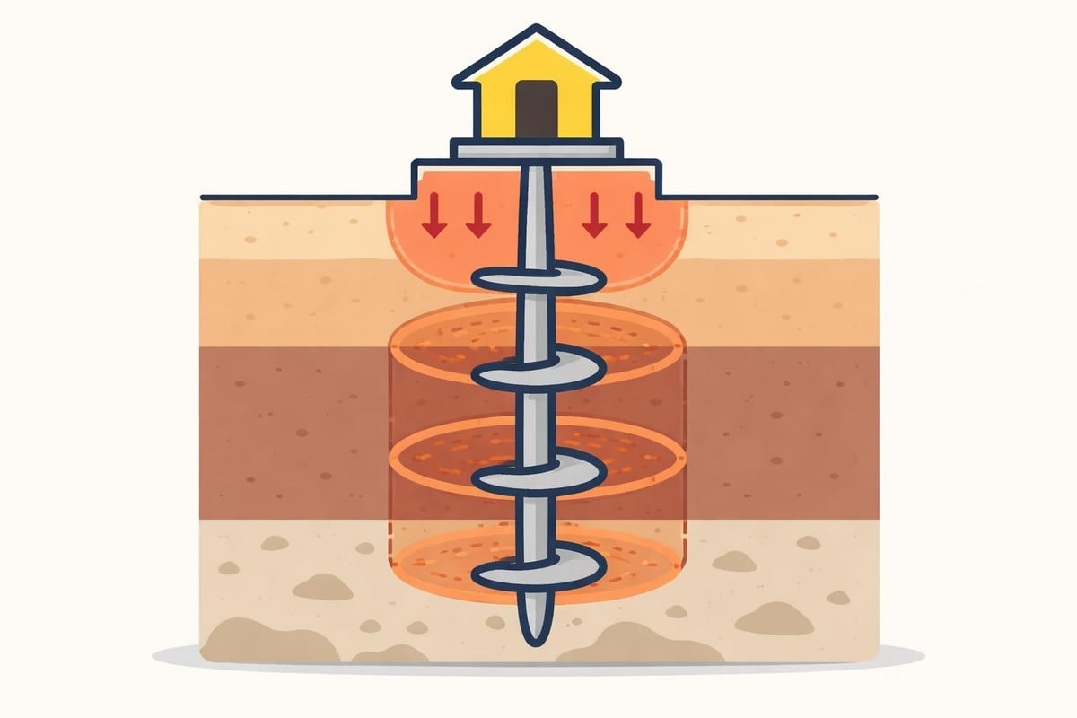
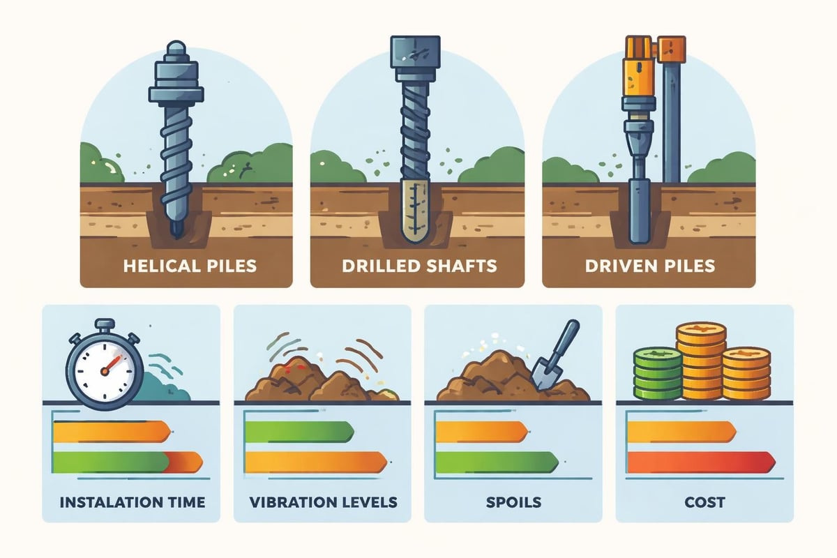
Helical piles have emerged as a versatile and efficient deep foundation solution for civil infrastructure, commercial development, and remedial construction projects. These engineered foundation elements consist of a central steel shaft with one or more helical bearing plates welded at specific intervals, installed into the ground by applying torque. Unlike conventional driven piles or drilled shafts, helical piles minimize vibration, generate minimal spoils, and can be installed in virtually any weather condition. Their growing adoption across North America reflects both technological advances in installation equipment and increased recognition of their performance advantages in challenging soil conditions. Understanding the design principles, installation requirements, and appropriate applications for helical piles enables engineers to deliver cost-effective foundation solutions that balance structural performance with constructability.
Foundation Mechanics and Load Transfer
Helical piles transfer structural loads to competent bearing strata through a combination of bearing capacity at the helix plates and shaft friction along the central steel member. The helical plates function as individual bearing elements, creating a series of cylindrical failure surfaces in the soil. Load distribution among multiple helices depends on helix spacing, soil properties, and the relative stiffness of the shaft.
Bearing Capacity Principles
The ultimate capacity of helical piles in compression is typically calculated using individual bearing methods or cylindrical shear methods. Individual bearing approaches treat each helix as a discrete shallow foundation, summing the contributions based on soil strength parameters at each helix depth. Cylindrical shear methods assume a soil cylinder forms between the top and bottom helix plates under loading, with capacity derived from the shear strength along this cylindrical surface and bearing at the lowest helix.
Key factors influencing bearing capacity:
- Helix diameter and spacing ratio
- Depth to competent bearing stratum
- Soil strength parameters (SPT N-values, CPT resistance, undrained shear strength)
- Number and configuration of helix plates
- Pile shaft diameter and stiffness
The Deep Foundations Institute provides comprehensive design guidance addressing both theoretical approaches and practical considerations for capacity calculations. Engineers must evaluate whether soil conditions support individual bearing behavior or if inter-helix spacing requires cylindrical shear analysis.
Tension Capacity Considerations
Helical piles perform exceptionally well in tension applications, making them ideal for tiebacks, foundation underpinning, and structures subject to uplift forces. Tension capacity derives from bearing resistance of the helix plates acting in reverse and shaft friction along the embedded length. The failure mechanism in tension typically involves either individual helix pullout or a cylindrical soil mass extraction.
Designing for tension requires careful attention to helix spacing and embedment depth. Minimum embedment ratios of five to seven times the helix diameter in competent material help ensure deep failure modes and predictable capacity. Shallow embedment may result in surface heaving or progressive failure through weaker surficial soils.
Design Methodology and Selection Criteria
Effective helical pile design integrates site-specific geotechnical data, structural loading requirements, and installation constraints. The process begins with thorough subsurface investigation to characterize soil stratigraphy, strength parameters, and groundwater conditions.
Geotechnical Investigation Requirements
Comprehensive soil investigation provides the foundation for defensible helical pile design. Borehole programs should extend below anticipated helix depths to confirm bearing layer continuity and identify potential installation obstacles such as cobbles, boulders, or refusal layers.
Standard penetration testing (SPT), cone penetration testing (CPT), and laboratory testing of recovered samples establish the strength parameters needed for capacity calculations. Understanding soil variability across the site allows engineers to optimize pile lengths and configurations while identifying areas requiring special installation procedures.
| Investigation Method | Primary Application | Data Provided |
|---|---|---|
| Standard Penetration Test | General soil profiling | N-values, soil classification, sampling |
| Cone Penetration Test | Continuous profiling | Tip resistance, sleeve friction, pore pressure |
| Laboratory Testing | Strength characterization | Shear strength, consolidation, classification |
| Test Pile Installation | Installation verification | Torque-capacity correlation, refusal depth |
The geotechnical team at firms specializing in specialized deep foundation piles conducts these investigations to support reliable foundation design and installation planning.
Load Testing and Verification
Load testing provides empirical verification of helical pile capacity and validates design assumptions. Compression and tension tests performed on production piles or dedicated test piles establish site-specific performance characteristics. The field testing procedures used for helical piles follow established protocols adapted from conventional deep foundation practice.
Common load testing approaches include:
- Quick load test procedures for preliminary capacity verification
- Maintained load tests following ASTM D1143 for compression
- Uplift load tests per ASTM D3689 for tension applications
- Proof testing on production piles at specified percentages of design load
Test results inform final design adjustments, validate installation torque correlation, and provide documentation for regulatory approval and quality assurance.
Installation Procedures and Quality Control
Helical pile installation represents a critical phase where design transitions to field execution. Proper installation techniques, equipment selection, and monitoring protocols ensure that installed capacity matches design expectations.
Equipment and Torque Monitoring
Installation equipment ranges from hand-held portable drives for light residential applications to high-torque hydraulic systems mounted on excavators or specialized drill rigs for commercial and industrial projects. Equipment selection depends on design torque requirements, site access constraints, and production rates.
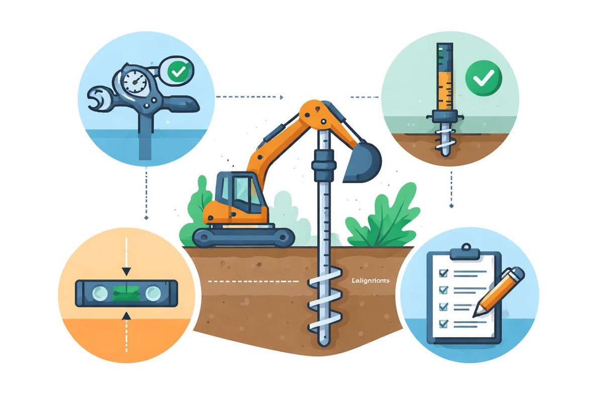
Real-time torque monitoring during installation provides immediate feedback on soil resistance and allows operators to verify that piles reach design depth with adequate embedment in bearing strata. Modern hydraulic systems incorporate digital torque readouts and data logging capabilities for quality documentation.
The empirical torque-capacity relationship forms the basis for installation acceptance criteria. The industry-standard correlation factor (Kt) relates installation torque to ultimate pile capacity, typically ranging from 3 to 10 depending on soil conditions and pile configuration. This relationship, expressed as Capacity = Kt × Torque, allows real-time capacity verification without load testing every pile.
Installation Challenges and Solutions
Site conditions occasionally present installation challenges requiring adaptive responses. Obstructions such as buried debris, cobbles, or dense glacial till may cause premature refusal or excessive deflection. Skilled operators recognize these conditions through torque irregularities and can implement corrective measures.
Common installation challenges:
- Premature refusal: Encountering obstructions above design depth requires assessment of alternative pile locations or pre-augering through obstruction zones
- Soft surface soils: Extending pile length to reach competent bearing layers while maintaining alignment
- Limited headroom: Selecting equipment with reduced height requirements or utilizing extension shafts
- Soil layering: Adjusting helix configuration to optimize load distribution across variable soil conditions
Quality control protocols document installation parameters for every pile, creating an archive that demonstrates compliance with design specifications and provides forensic data if performance questions arise. This documentation typically includes pile location, final depth, final installation torque, and any installation anomalies encountered.
Applications Across Civil Infrastructure
Helical piles serve diverse applications across the civil engineering spectrum, from new construction to remedial repair projects. Their versatility stems from the ability to customize shaft and helix configurations for specific loading conditions and the minimal site disturbance during installation.
New Construction Foundations
Commercial and industrial building foundations frequently utilize helical piles where shallow foundations prove inadequate due to weak surficial soils or high water tables. Light-frame structures, pre-engineered metal buildings, and additions to existing facilities benefit from the rapid installation and immediate load capacity of helical piles.
Foundation systems for equipment pads, retaining walls, and modular structures rely on helical piles to provide stable support without extensive excavation or dewatering. The design guide developed by industry experts outlines systematic approaches for sizing and configuring piles across various structural applications.
Transportation infrastructure incorporates helical piles for sign and signal foundations, sound barrier walls, and pedestrian bridge supports. The minimal right-of-way disruption and fast installation align with the constraints of active transportation corridors.
Remedial and Underpinning Projects
Existing structures experiencing settlement or requiring capacity upgrades present ideal applications for helical piles. Underpinning operations using helical piles can be completed from inside occupied buildings with minimal vibration or noise, allowing business continuity during foundation repairs.
Retrofit projects benefit from the precision load transfer and controlled installation that helical piles provide. Bracket systems connect new piles to existing footings, transferring structural loads while limiting additional settlement. Historical preservation projects value the non-destructive installation and reversibility of helical pile systems.
Material Specifications and Durability
Helical pile components must satisfy structural capacity requirements while providing adequate service life in the anticipated soil and groundwater environment. Material selection balances strength, weldability, and corrosion resistance based on project-specific demands.
Structural Steel Requirements
Central shafts typically consist of solid square bar, round bar, or pipe sections fabricated from ASTM A36, A572, or A500 steel. Helix plates are cut from structural plate meeting ASTM A572 Grade 50 or equivalent specifications. Welds connecting helices to shafts require full penetration with appropriate inspection and quality control.
| Component | Material Specification | Typical Yield Strength |
|---|---|---|
| Square shaft | ASTM A572 Grade 50 | 50 ksi |
| Round shaft | ASTM A36 | 36 ksi |
| Pipe shaft | ASTM A500 Grade B/C | 42-50 ksi |
| Helix plates | ASTM A572 Grade 50 | 50 ksi |
Shaft diameter selection considers both structural capacity under axial and lateral loading and torsional strength during installation. Engineers must verify that shaft sections can withstand installation torque without yielding or buckling, particularly in dense soil conditions requiring high installation effort.
Corrosion and Longevity
Service life projections for helical piles account for general corrosion in soil and groundwater environments. Research on steel pile corrosion indicates that uniform corrosion rates in most natural soils range from 0.001 to 0.004 inches per year. Design practices incorporate sacrificial steel thickness or protective coatings when site conditions indicate aggressive corrosive environments.
Corrosion mitigation strategies include:
- Galvanized coatings (hot-dip or mechanical plating) for enhanced protection
- Epoxy or polyurethane coatings in highly acidic or contaminated soils
- Increased shaft diameter to provide sacrificial steel thickness
- Cathodic protection systems for critical permanent structures
The historical development and performance of screw piles demonstrates that properly designed systems achieve service lives exceeding 50 years in typical soil conditions. Accelerated corrosion may occur in organic soils with low pH, industrial fill containing aggressive chemicals, or marine environments with sulfate-reducing bacteria.
Regulatory Compliance and Approval
Building code acceptance of helical piles requires compliance with relevant design standards and product evaluation reports. Jurisdictions across North America reference model codes that incorporate helical pile provisions based on industry consensus documents.
Code Recognition and Evaluation Reports
The International Building Code (IBC) and International Residential Code (IRC) provide performance-based criteria for deep foundation design, including allowable stress design and load and resistance factor design (LRFD) approaches. Helical pile manufacturers typically obtain evaluation service reports documenting ICC-ES approval for their proprietary products and installation systems.
These evaluation reports establish allowable loads, installation requirements, and quality assurance provisions recognized by building officials. Engineers reference specific evaluation reports in construction documents, ensuring that installed products match approved systems. The ICC-ES report process involves third-party review of product testing, manufacturing quality control, and installation procedures.
Project specifications should clearly define acceptance criteria, testing requirements, and installation tolerances. Coordination between designers, installers, and inspection authorities early in project planning prevents conflicts during construction and facilitates timely approvals.
Comparative Performance and Economics
Selecting appropriate foundation systems requires evaluating technical performance against project constraints and budget. Helical piles compete with conventional driven piles, drilled shafts, and shallow foundations across various metrics.
Installation Efficiency
Helical piles offer significant time advantages over drilled shaft construction and driven pile operations. Typical installation rates range from 15 to 30 piles per day with a single crew, compared to 5 to 10 drilled shafts or similar driven pile production. Immediate load capacity eliminates concrete curing time, allowing same-day structural erection.
Mobilization costs for helical pile installation equipment typically run lower than pile driving rigs or drilling operations requiring support equipment. Smaller crews and reduced site preparation contribute to overall project economy, particularly for projects with limited pile counts.
Environmental and Site Impact
Urban and environmentally sensitive sites benefit from the minimal disturbance associated with helical pile installation. Vibration levels during installation remain negligible compared to impact driving, preventing damage to adjacent structures and eliminating nuisance complaints. Spoil generation is eliminated, avoiding disposal costs and contaminated soil handling in brownfield redevelopment.
These environmental advantages align with sustainability goals and facilitate permitting in jurisdictions with stringent construction impact regulations. The ability to work in close proximity to existing utilities, wetlands, and occupied structures expands the range of feasible project sites.
Advanced Applications and Innovations
Emerging applications and technological developments continue to expand the role of helical piles in modern construction. Designers increasingly recognize opportunities to optimize foundation performance through hybrid systems and specialized configurations.
Combined Loading and Lateral Capacity
While helical piles excel in axial loading applications, their lateral capacity requires careful evaluation. Lateral loads induce bending moments in the shaft and mobilize passive soil resistance. Shaft stiffness and diameter significantly influence lateral performance, with larger diameter shafts providing greater resistance to deflection.
Design for combined axial and lateral loading follows interaction equations that account for reduced capacity under simultaneous load components. Some applications incorporate grade beams or pile caps to distribute lateral forces among multiple piles, improving system performance.
Tieback and Earth Retention Systems
Helical anchors function as tension elements for earth retention systems, providing economical alternatives to grouted anchors or deadman systems. Temporary excavation support during construction and permanent tiebacks for retaining walls benefit from rapid installation and immediate proof testing capability.
The ability to install anchors at various inclinations and achieve predictable tension capacity makes helical systems attractive for challenging geotechnical conditions. Design considerations include adequate embedment in stable soil, appropriate helix sizing for tension loads, and corrosion protection for permanent installations.
Technical Resources and Continuing Education
Professionals involved in helical pile design, specification, or installation benefit from ongoing education and access to industry resources. Technical publications, professional organizations, and manufacturer support provide pathways for maintaining current knowledge.
The comprehensive design and installation guide authored by recognized experts serves as a definitive reference for engineers and contractors. This resource covers theoretical foundations, practical design procedures, and case histories illustrating successful applications.
Industry associations maintain technical committees focused on advancing helical pile technology and standardizing design practice. Resources available through professional networks include webinars, technical papers, and forums for discussing field challenges and innovative solutions.
Manufacturers offer training programs covering product specifications, installation techniques, and troubleshooting procedures. These programs help installers achieve consistent quality and enable design professionals to understand capabilities and limitations of specific systems. The practical design guidelines available from industry sources provide accessible tools for everyday engineering practice.
Continuing development in installation monitoring technology, capacity prediction methods, and product innovation ensures that helical piles will remain a dynamic and evolving foundation solution for the foreseeable future.
Helical piles deliver proven foundation performance across diverse civil infrastructure applications through efficient installation, reliable capacity, and minimal environmental impact. Their versatility in tension and compression loading, combined with rapid construction schedules, makes them an increasingly valuable tool for addressing challenging site conditions. Whether your project involves new construction foundations, remedial underpinning, or specialized earth retention systems, ZALIG Consulting Ltd provides the integrated geotechnical investigation, foundation engineering, and construction support services needed to implement successful helical pile solutions. Our multidisciplinary team collaborates with clients from initial site assessment through design optimization and field verification, delivering practical foundation systems that manage risk and support project success.