

Engineering design balances performance with protection. Every structure, foundation, and component must carry its intended load while maintaining an adequate buffer against failure. This buffer, quantified as the factor of safety, represents one of the most fundamental concepts in engineering practice. It ensures that real-world uncertainties, material variability, and unexpected conditions don't compromise structural integrity. For professionals managing civil infrastructure projects, understanding how to properly apply this principle directly impacts project success, regulatory compliance, and public safety.
Understanding the Factor of Safety Concept
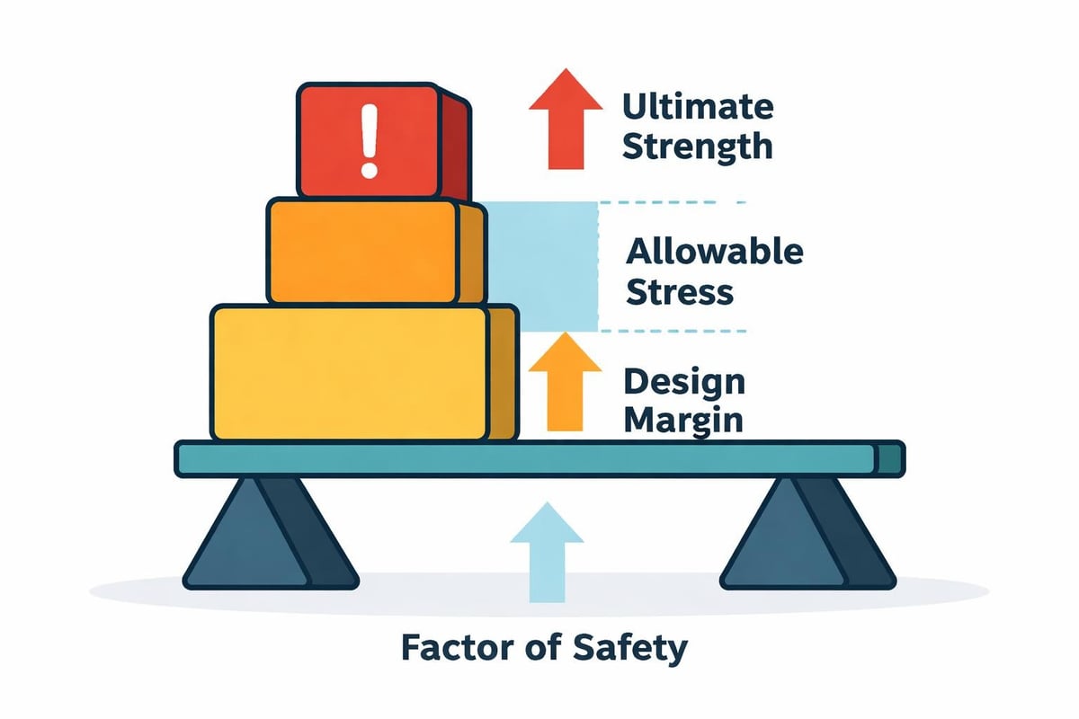
The factor of safety serves as a ratio between a system's ultimate capacity and the actual demand placed upon it. Engineers use this dimensionless number to account for unknowns that exist in every project, from material property variations to construction quality differences.
At its core, the calculation compares strength to stress. Ultimate strength represents the maximum load a material or structure can withstand before failure. Allowable stress defines the maximum stress permitted under design conditions. The ratio between these values creates the safety margin.
Mathematical Foundation
The basic formula expresses factor of safety as:
FoS = Ultimate Strength / Allowable Stress
Alternatively, engineers express it through load capacity:
FoS = Load Capacity / Applied Load
When the factor of safety equals 1.0, the structure operates at its absolute limit. Any value below 1.0 indicates imminent failure. Professional practice demands values substantially higher than unity to accommodate real-world conditions.
Several calculation variations exist depending on the application:
- Yield-based FoS uses yield strength as the failure criterion for ductile materials
- Ultimate-based FoS applies ultimate tensile strength for brittle materials
- Buckling-based FoS considers critical buckling load for compression members
- Fatigue-based FoS incorporates cyclic loading effects over time
Industry-Standard Values and Selection Criteria
Different engineering disciplines and applications require different safety margins. Typical factor of safety values range from 1.5 to 10 depending on multiple variables including consequence of failure, load predictability, and material certainty.
| Application Area | Typical FoS Range | Primary Considerations |
|---|---|---|
| Steel structures | 1.5 – 2.5 | Well-understood properties, ductile behavior |
| Concrete foundations | 2.0 – 3.0 | Material variability, construction quality |
| Geotechnical slopes | 1.3 – 1.5 | Soil variability, water table fluctuations |
| Pressure vessels | 3.5 – 4.0 | Catastrophic failure consequences |
| Aircraft components | 1.5 – 2.0 | Weight constraints, rigorous testing |
| Lifting equipment | 5.0 – 10.0 | Dynamic loads, human safety |
Selection Factors
Choosing an appropriate factor of safety requires evaluating several critical elements. Material properties knowledge significantly influences the decision-well-characterized materials with minimal variation permit lower factors, while materials with uncertain properties demand higher values.
Load predictability plays an equally important role. Static loads with precise magnitudes allow tighter margins. Dynamic, cyclic, or impact loads introduce uncertainty requiring larger safety buffers.
The consequence of failure often dominates selection. Structures where failure risks human life require substantially higher factors than those where failure causes only economic loss. This explains why geotechnical applications often employ different criteria than structural steel design.
Regulatory requirements and building codes frequently mandate minimum values. Professional engineers must balance code compliance with project-specific conditions.
Application in Geotechnical Engineering
Geotechnical design presents unique challenges that make the factor of safety particularly critical. Soil and rock properties exhibit natural variability that exceeds most manufactured materials. Subsurface conditions change spatially and temporally, influenced by moisture content, seasonal effects, and construction disturbance.
Foundation design relies on safety factors to address this inherent uncertainty. Engineers select values based on investigation quality, soil type, and loading conditions. A shallow foundation on well-characterized dense sand might use FoS of 2.5, while a similar foundation on variable clay deposits could require 3.0 or higher.
Slope Stability Analysis
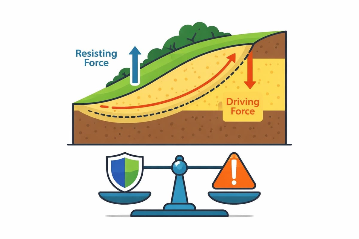
Slope stability calculations exemplify practical factor of safety application. Engineers compare resisting forces (soil shear strength along potential failure surfaces) against driving forces (gravitational component parallel to the slope).
The analysis typically proceeds through these steps:
- Define soil geometry and layer boundaries from site investigation
- Identify potential failure surfaces using circular or non-circular methods
- Calculate driving moments from soil weight and external loads
- Calculate resisting moments from soil shear strength parameters
- Compute FoS as ratio of resisting to driving moments
For natural slopes, minimum factors typically range from 1.3 to 1.5. Engineered cuts and fills often require 1.5 or higher. These seemingly modest values reflect the difficulty in precisely characterizing soil properties and the progressive nature of many geotechnical failures.
When ZALIG Consulting Ltd performs geotechnical investigations, our field testing and laboratory analysis provide the strength parameters essential for defensible factor of safety calculations in foundation and slope designs.
Bearing Capacity Considerations
Foundation bearing capacity design incorporates safety factors to prevent both shear failure and excessive settlement. The ultimate bearing capacity represents the theoretical maximum pressure before foundation failure. Dividing this value by the factor of safety yields the allowable bearing pressure used in design.
Engineers must consider whether failure is sudden (bearing capacity) or progressive (settlement). Different factors may apply to each mode, with settlement often controlling in compressible soils.
Structural Engineering Applications
Structural design codes incorporate factor of safety principles through Load and Resistance Factor Design (LRFD) and Allowable Stress Design (ASD) methodologies. While the modern LRFD approach applies separate factors to loads and resistances, the underlying concept remains consistent-ensuring capacity exceeds demand with adequate margin.
Steel structure design benefits from well-defined material properties and ductile behavior. Factors of 1.67 on yield strength are common in ASD, translating to allowable stresses of approximately 60% of yield. LRFD achieves similar reliability through resistance factors around 0.90 combined with load factors of 1.2 to 1.6.
Concrete design requires higher safety margins due to material variability and brittle failure modes in some conditions. Unreinforced concrete may use factors of 3.0 or more, while properly reinforced sections use lower values due to redundancy and ductility.
Connection and Fastener Design
Bolted and welded connections often employ higher factors than primary members. This practice ensures that failure occurs in members rather than connections, allowing for more predictable and observable failure modes. Connection factors might reach 2.0 to 2.5 even when member factors are lower.
The importance of factor of safety in connection design reflects the concentration of stress and potential for sudden, brittle failure at these critical locations.
Material-Specific Considerations
Different materials require different approaches to safety factors based on their mechanical behavior and failure characteristics.
Ductile versus Brittle Materials
Ductile materials like structural steel exhibit significant deformation before failure, providing visual warning and load redistribution capacity. This behavior justifies lower safety factors, typically 1.5 to 2.5 for static loads.
Brittle materials including cast iron, glass, and unreinforced concrete fail suddenly without warning. Higher factors of 3.0 to 6.0 compensate for this unpredictability.
| Material Category | Failure Behavior | Typical FoS | Design Basis |
|---|---|---|---|
| Structural steel | Ductile, yielding | 1.67 – 2.0 | Yield strength |
| Aluminum alloys | Ductile, yielding | 1.65 – 2.0 | Yield strength |
| Timber | Semi-ductile | 2.0 – 3.0 | Ultimate strength |
| Concrete (reinforced) | Ductile system | 1.5 – 2.0 | Compressive strength |
| Concrete (unreinforced) | Brittle | 3.0 – 4.0 | Compressive strength |
| Cast iron | Brittle | 4.0 – 6.0 | Ultimate strength |
Composite and Advanced Materials
Modern composite materials present unique challenges. Their properties depend on fiber orientation, manufacturing quality, and environmental exposure. Engineers often employ factors of 2.0 or higher until extensive testing establishes confidence in specific applications.
Carbon fiber reinforced polymers used in structural rehabilitation may require factors adjusted for long-term durability concerns and fire resistance limitations.
Dynamic and Cyclic Loading Effects
Static load calculations represent the simplest case. Real structures experience dynamic effects from wind, seismic activity, machinery vibration, and vehicle loads. These conditions demand modified approaches to safety factors.
Impact and Shock Loading
Impact loads deliver energy rapidly, creating stress waves and localized yielding that static analysis doesn't capture. Design for impact typically involves:
- Increasing the effective load through dynamic amplification factors
- Reducing allowable stress through lower factor of safety application
- Combining both approaches for severe impact conditions
Construction equipment operating on temporary structures exemplifies this concern. A crane boom swing impact might require analyzing the scenario with both doubled loads and increased safety factors.
Fatigue Considerations
Cyclic loading causes progressive damage accumulation even at stress levels well below static capacity. Understanding factor of safety in fatigue requires examining stress range rather than absolute stress magnitude.
Fatigue design often employs separate criteria:
- Infinite life design keeps stress ranges below the endurance limit
- Finite life design permits higher stresses with defined inspection and replacement intervals
- Damage-tolerant design assumes cracks exist and prevents catastrophic propagation
Welded connections in bridges and industrial structures particularly require fatigue evaluation with appropriate safety factors applied to stress range calculations.
Environmental and Degradation Factors
Material properties change over time due to environmental exposure. Corrosion, weathering, ultraviolet degradation, and chemical attack reduce capacity, effectively decreasing the factor of safety throughout a structure's life.
Corrosion allowances in steel design add extra thickness to compensate for expected metal loss. Alternatively, protective coatings and cathodic protection systems maintain capacity. The initial factor of safety must account for end-of-service conditions, not just initial installation.
Temperature effects alter material strength and stiffness. High temperatures reduce steel and polymer strength significantly. Low temperatures increase concrete and steel brittleness. Design factors should reflect the full service temperature range.
Soil properties change with moisture content variation. In-situ geotechnical testing during different seasons helps characterize this variability, enabling more accurate safety factor selection for foundation and earth structure design.
Regulatory Framework and Code Requirements
Building codes and industry standards establish minimum factor of safety values to ensure public welfare. These requirements reflect consensus judgment about acceptable risk levels in different applications.
National and international codes include:
- American Concrete Institute (ACI) standards for concrete structures
- American Institute of Steel Construction (AISC) specifications for structural steel
- American Association of State Highway and Transportation Officials (AASHTO) for bridge design
- International Building Code (IBC) for general construction
- Canadian Standards Association (CSA) standards for Canadian projects
Each code balances safety with economy, adjusting factors based on decades of performance data and failure investigations. Engineers must understand which codes govern their projects and apply the specified factors correctly.
Professional Responsibility
Licensed professional engineers bear legal and ethical responsibility for safety factor selection. While codes provide minimums, site-specific conditions may warrant higher values. This judgment call requires:
- Thorough understanding of loading conditions and material properties
- Recognition of uncertainties in analysis and construction
- Consideration of failure consequences
- Documentation of decisions and assumptions
The definition and application of factor of safety ultimately rests on professional judgment within the regulatory framework.
Practical Design Process Integration
Incorporating factor of safety into real projects requires systematic evaluation at multiple stages. Preliminary design uses conservative factors with estimated properties. As investigation data improves and analysis becomes more detailed, factors can be refined.
Design Iteration Workflow
Effective design follows this general progression:
- Preliminary assessment with conservative FoS values and simplified analysis
- Detailed investigation providing better material and loading data
- Refined analysis using project-specific properties and conditions
- Code compliance check verifying minimum factors are met or exceeded
- Constructability review ensuring the design can be built as intended
- Inspection and testing protocols to verify assumptions during construction
This iterative approach balances safety with efficiency. Over-conservative initial factors provide protection during early stages when uncertainty is highest. Refinement optimizes the design while maintaining appropriate margins.
Value Engineering Considerations
Value engineering aims to reduce cost without sacrificing performance or safety. Factor of safety decisions significantly impact material quantities and construction methods. Reducing factors requires:
- Enhanced investigation to reduce property uncertainty
- Improved analysis methods providing more accurate predictions
- Better quality control during construction
- Monitoring provisions to verify performance
These investments must be weighed against savings from reduced material usage or simplified construction. The minimum acceptable factor remains constrained by code requirements and professional judgment.
Common Mistakes and How to Avoid Them
Even experienced engineers occasionally misapply safety factors, leading to unconservative or excessively conservative designs. Awareness of common errors helps prevent problems.
Mistake 1: Applying factors to factored loads
Load combinations in modern codes already include load factors. Applying additional safety factors to these factored loads creates unintentional double-factoring. Always verify whether loads are service-level or factored before applying resistance factors.
Mistake 2: Inconsistent factor application
Different failure modes may control under different conditions. Apply appropriate factors to each mode separately rather than assuming one governs all cases. Settlement and bearing capacity, for example, require independent evaluation.
Mistake 3: Ignoring construction sequence
Temporary construction conditions sometimes prove more critical than final service loads. Formwork support, excavation shoring, and construction equipment access require separate factor of safety evaluation with construction-appropriate values.
Mistake 4: Misunderstanding characteristic versus design values
Material strengths reported in laboratory testing represent characteristic values, often at specific percentile levels (5th percentile is common). Design strengths apply additional factors to these characteristic values. Using test results directly without appropriate factors undermines safety.
Mistake 5: Neglecting load combinations
Maximum load from one source rarely coincides with maximum load from another. Codes specify load combination rules that may permit reduced factors when multiple transient loads are combined, recognizing the low probability of simultaneous occurrence.
Integration with Risk Management
Modern engineering practice views factor of safety as one component within broader risk management frameworks. Probabilistic methods complement traditional deterministic approaches, providing additional insight into reliability and failure probability.
Reliability-based design quantifies uncertainty in both loads and resistances as probability distributions rather than single values. The analysis computes failure probability, which correlates to traditional safety factors but provides more nuanced understanding.
A structure with FoS of 2.0 might have vastly different reliability depending on the variability of its loads and materials. Low variability could yield very low failure probability. High variability might produce concerning failure rates despite the same nominal factor.
LRFD methodologies represent a bridge between traditional factors and full probabilistic analysis. Separate factors on loads and resistances calibrate to target reliability levels while maintaining familiar calculation procedures.
This evolution doesn't eliminate factor of safety but enhances its application. Engineers can make better-informed decisions about when standard factors suffice and when conditions warrant additional conservatism or detailed probabilistic evaluation.
Testing and Verification Programs
Design calculations predict behavior, but testing validates assumptions. Appropriate testing programs provide confidence that actual factors of safety meet or exceed design intent.
Material testing verifies that construction materials meet specified properties. Concrete cylinder testing, soil compaction verification, and steel mill certifications confirm the strength values used in factor of safety calculations.
Proof loading applies known loads to completed structures, demonstrating capacity before full service begins. Bridge load testing and pile load testing exemplify this approach. The test load typically reaches some fraction of the design load, with successful performance confirming adequate safety margins.
Monitoring programs track long-term performance, detecting degradation or unexpected behavior before factors of safety diminish below acceptable levels. Settlement monitoring on foundations, crack monitoring on concrete structures, and corrosion inspection on steel elements provide early warning of problems.
When ZALIG provides construction materials testing services, the field and laboratory verification ensures that designed factors of safety translate into actual structural performance, giving owners confidence in long-term reliability.
Factor of Safety in Specialty Applications
Certain engineering applications face unique conditions requiring specialized factor of safety approaches.
Seismic Design
Earthquake loading represents one of the most challenging design scenarios. Ground motion intensity, duration, and frequency content vary dramatically. Most codes permit capacity design approaches where certain elements are allowed to yield in controlled ways, effectively reducing factors of safety temporarily while maintaining overall structural integrity through ductility and energy dissipation.
Marine and Offshore Structures
Structures in marine environments face wave loading, current forces, and corrosive conditions simultaneously. The factor of safety definition and application must account for combined environmental effects, access limitations for inspection and maintenance, and catastrophic consequences of failure in remote locations. Factors of 2.5 to 3.5 are common, with higher values for critical components.
Underground Excavations
Tunnels, mines, and deep basements operate in a regime where the ground provides both loading and support. Classical factor of safety concepts require adaptation. Support systems may use factors of 2.0 or higher, but the approach also incorporates observational methods where initial support is augmented based on monitored behavior.
Temporary Structures
Scaffolding, formwork, and construction shoring serve limited durations but pose significant risk during use. Some jurisdictions mandate factors of 3.0 to 4.0 for these applications despite their temporary nature, recognizing the uncertainty in construction loading and the vital importance of worker safety.
Understanding and correctly applying factor of safety principles remains fundamental to engineering practice across all disciplines. The concept provides a rational framework for managing uncertainty while delivering structures and systems that perform reliably throughout their service lives. Whether you're evaluating foundation capacity, analyzing slope stability, or designing drainage infrastructure, selecting appropriate safety margins requires balancing code requirements, material properties, loading conditions, and consequence of failure. ZALIG Consulting Ltd brings multidisciplinary expertise to help clients navigate these decisions across geotechnical, structural, environmental, and civil infrastructure projects, delivering practical solutions that manage risk and support successful project outcomes from investigation through construction.